Printed Circuit Board (PCB) design is the intricate art and science of creating the electronic pathways that power our modern devices.
From smartphones and laptops to medical equipment and spacecraft, PCBs are the unsung heroes of our technological world.
Learning PCB design empowers you to bring your electronic ideas to life, transforming concepts into tangible circuits that can solve problems and drive innovation.
Whether you’re a hobbyist, a student, or a professional engineer, mastering PCB design opens doors to a world of creative and technical possibilities.
However, navigating the vast landscape of online PCB design courses can be overwhelming, especially on platforms like Udemy, which boasts a plethora of options.
You’re looking for a course that not only covers the fundamental principles but also provides hands-on experience with industry-standard software, practical projects, and clear guidance from experienced instructors.
The ideal course should equip you with the skills and confidence to design, manufacture, and troubleshoot your own PCBs.
After reviewing numerous PCB design courses on Udemy, we’ve identified Crash Course Electronics and PCB Design as the best overall course.
This comprehensive program delves into both the theoretical and practical aspects of electronics and PCB design, offering a deep dive into circuit analysis, component selection, schematic capture, and PCB layout.
The course’s hands-on approach, coupled with its focus on real-world projects, ensures you gain a solid foundation and practical experience that you can apply to your own endeavors.
While Crash Course Electronics and PCB Design is our top recommendation, there are several other excellent PCB design courses on Udemy that cater to specific needs and learning styles.
Continue reading to explore our curated list of top courses, each offering a unique approach to mastering this essential skill.
We’ll cover options for beginners, those seeking advanced techniques, and courses focusing on specific PCB design software like Altium Designer, KiCad, and Eagle.
Crash Course Electronics and PCB Design
This massive course covers both the theory and practical aspects of electronics and PCB design in incredible depth.
The syllabus is structured to start from the basics of electronics components like resistors, capacitors, and inductors.
It then builds up layer by layer, covering analog and digital circuit analysis techniques, semiconductor devices like diodes and transistors, digital logic design, programmable logic, microcontrollers, and finally printed circuit board (PCB) design and manufacturing.
The unique strength of this course lies in its hands-on approach.
You won’t just learn the theory - the lectures are accompanied by numerous bench experiments, circuit simulations, and three full PCB design projects.
These allow you to apply the concepts practically and develop a deep understanding from the ground up.
The syllabus covers fundamental topics like Ohm’s law, Kirchhoff’s laws, Boolean algebra, and AC/DC circuit analysis.
It then dives into advanced subjects like complex impedance, phasor analysis, operational amplifiers, transistor amplifiers, logic families, programmable logic, and much more.
The course even touches on niche areas like conductive inks and hacking techniques.
What sets this course apart is the end-to-end PCB design process you’ll go through for three projects - a magic wand, a 555-based organ, and an Arduino-based “SimonDuino” game console.
You’ll learn how to install and use the CircuitMaker software, do schematic entry, component placement, PCB routing, generate manufacturing files, and more.
This is invaluable practical experience that most electronics courses lack.
The syllabus is very comprehensive, yet the lecture descriptions suggest the instructor will explain concepts clearly and gradually build up your knowledge.
There are also many “bonus lectures” that cover random interesting electronics topics like motor drivers, audio amplifiers, power supplies, test equipment selection, and even some career advice.
The course combines rigorous electronics theory with extensive practical PCB design experience.
You’ll develop a strong foundation while learning directly applicable skills for building real-world electronics products.
The hands-on approach and project-based learning make this a standout option among electronics courses.
PCB design with Altium Designer
You’ll start with the fundamentals of schematic design, learning how to create projects, define properties, and add components from libraries.
You’ll also learn how to filter components, design schematics effectively, and document your work thoroughly.
The course then guides you through the process of creating custom libraries for both schematic and PCB components, a valuable skill for more complex designs.
You’ll learn to design power supplies, create custom footprints, and annotate designators to organize your work.
You’ll also gain practical experience in PCB layout, including adding schematic components, aligning components and pads, and understanding routing and design rules.
The course covers advanced topics like multilayer design, enabling you to create complex boards, and introduces 3D modeling for visualizing and planning your projects.
One of the most valuable aspects of the course is the hands-on approach.
You’ll work on real-world projects, such as a fire system, getting hands-on experience with the practical applications of PCB design.
You’ll also be introduced to Gerber files, an essential format for manufacturing, and learn how to perform design rule checks to ensure your designs meet industry standards.
The course concludes with access to a library of components used throughout the course, providing a valuable starting point for your own projects.
This course gives you the knowledge and skills you need to confidently design and manufacture your own PCBs.
PCB design with KiCad - updating for KiCad 8
This comprehensive course dives deep into the world of PCB design using KiCad, focusing specifically on the latest version, KiCad 8.
You’ll start by gaining a solid understanding of the fundamentals, learning what a PCB is, and how the design process works from start to finish.
Then, you’ll jump right into the software itself, getting hands-on experience with the user interface and the various tools available.
You’ll build confidence as you tackle a series of hands-on projects, starting with a simple breadboard power supply PCB.
This helps you solidify your understanding of the entire design workflow, from schematic creation to layout and manufacturing.
As you progress, you’ll move on to more complex projects, like a datalogger with built-in EEPROM and a clock, expanding your skills and knowledge.
You’ll become proficient in using essential tools like Eeschema for schematic design and Pcbnew for layout design.
You’ll learn how to create custom symbols and footprints, utilize libraries for efficiency, and apply design rules to ensure optimal circuit functionality.
You’ll even delve into advanced topics like autorouting with Freerouting and utilizing Git for project management.
Throughout the course, you’ll explore design principles, learn about various PCB materials, and gain a deep understanding of crucial elements like traces, vias, and solder masks.
You’ll learn how to create Gerber files, export your designs for manufacturing, and even master the intricacies of four-layer PCB design.
The course also provides valuable guidance on troubleshooting design defects and incorporating 3D shapes for your projects.
Learn the Art and Science of PCB Design with Eagle
You’ll start by learning the fundamentals of printed circuit boards, mastering Eagle’s software installation, and creating your first project.
The course guides you through the creation of single-sided PCBs, covering essential skills like schematic design, component placement, layer management, and adding labels and names to your designs.
You’ll gain practical experience with a hands-on single-sided PCB project and then tackle the challenge of building a microcontroller-based PCB in three phases.
The course doesn’t shy away from more advanced concepts.
You’ll learn about copper pours, a technique essential for efficient circuit board design.
The course then delves into double-sided PCB design, incorporating surface mount devices (SMTs), and even teaches you to create custom library parts, giving you complete control over your design process.
The course covers the use of autorouters, a powerful tool that simplifies the routing process, making your design more efficient.
Finally, you’ll learn about the manufacturing process, including generating Gerber files, bills of materials, and printing single-sided PCBs.
You’ll also gain experience creating PCB artwork, with a specific project focused on an electronic cricket match circuit.
This course is a thorough introduction to PCB design with Eagle, covering everything from basic concepts to advanced techniques.
You’ll be equipped to design both single-sided and double-sided PCBs, confidently incorporate SMT components, and master the art of copper pouring and autorouting.
You’ll walk away with the knowledge and skills needed to bring your electronic ideas to life.
PCB Design in Cadence OrCAD/Allegro: Basics to Expert level
You’ll gain a solid understanding of Printed Circuit Boards (PCBs) themselves, including their types, classes, and levels, along with a detailed overview of the manufacturing process.
The course dives deep into Cadence OrCAD/Allegro software, teaching you how to create new projects, navigate the environment, and customize your design preferences.
You’ll learn to create electronic symbols according to IEEE standards, ensuring accuracy and professionalism in your schematics.
You’ll then master schematic creation using OrCAD Capture, learning about wiring nets, global connections, and preparing multi-page schematics.
The course also emphasizes the importance of Electrical Rule Checking (ERC) and Bill of Material (BOM) preparation, crucial for maintaining design integrity.
Next, you’ll delve into footprint creation, designing the physical layout of electronic components on the PCB.
The course covers both Surface Mount Device (SMD) and Through-Hole (THT) footprint design, with detailed instructions for creating footprints for various component packages like SOIC, PDIP, PLCC, and BGA.
Finally, you’ll transition to PCB design, learning how to define board shapes, place components, and implement routing techniques.
You’ll also gain proficiency in using VIAs, including creating different VIA types, like blind and buried VIAs, which are essential for connecting different layers of the PCB.
The course concludes with practical assignments that allow you to apply your knowledge.
You’ll design a 2-layer PCB and then graduate to a more complex 4-layer PCB, gaining valuable real-world experience.
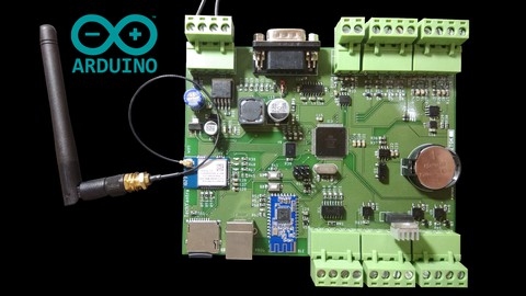
Arduino : Electronics circuit, PCB Design & IOT Programming
This course takes you on a journey from understanding basic electronics to designing and building your own custom PCBs.
You’ll learn about fundamental components like resistors, capacitors, and transistors, and delve into more complex concepts like voltage level converters and SMPS power supplies.
The course doesn’t just focus on theory, though.
You’ll gain hands-on experience with the widely-used Eagle software to design your own PCB layouts, and you’ll learn how to use the Arduino IDE to program microcontrollers for different applications.
You’ll learn to program essential functions, like PWM for controlling motor speed, and use interrupts to respond to external events, creating interactive circuits.
The course covers a wide range of communication protocols, including UART, SPI, I2C, RS232, and RS485, teaching you how to send and receive data, making your devices capable of interacting with other systems.
You’ll use a logic analyzer to visualize these signals, allowing you to understand and debug your circuits effectively.
This course goes beyond the basics, exploring more advanced concepts like designing a custom protocol to communicate with your devices.
You’ll also learn how to connect your creations to the internet using WIFI and Bluetooth Low Energy modules, opening up a world of possibilities for remote control and data collection.
The course includes sections on data visualization, allowing you to analyze and display the information gathered by your circuits.
This course offers a well-rounded experience, covering both the hardware and software aspects of building your own custom electronics projects.
You’ll walk away with a strong foundation in electronics, PCB design, and programming, equipped to tackle a variety of exciting projects.
PCB Design a Tiny Arduino In Altium CircuitMaker
You’ll start by getting hands-on with Altium Circuit Maker, a powerful software that will become your primary tool.
The course takes you through a structured learning journey, starting with the fundamentals of schematic design.
You’ll learn to add essential components, like the Arduino Nanite, which acts as the heart of your project, and connect them with virtual wires.
Key concepts like assigning designators, compiling your design, and ensuring a clean, professional schematic are emphasized throughout this initial phase.
The real excitement begins when you move into printed circuit board design.
This section guides you through importing components, defining your board’s shape, and carefully placing components onto the Arduino Nanite.
You’ll discover the critical importance of design rule checking, a process that ensures proper spacing and alignment, preventing potential issues during manufacturing.
The course goes beyond the basics, exploring techniques for optimizing component placement to create compact and efficient designs.
You’ll learn to master both manual and automated routing methods, connecting components on your board with precise copper traces.
One of the course’s strengths is its focus on preparing you for actual board fabrication.
You’ll learn to generate Gerber files, which define the intricate copper layers and other elements on your board, and NC drill files, which specify where holes need to be drilled.
The process of creating a Bill of Materials (BOM) – a detailed list of every component needed for your project – is also covered thoroughly.
These skills are essential for bringing your PCB designs to life, making this course particularly valuable for those interested in building working prototypes.
Designing PCB using Autodesk Eagle for Everyone!
You’ll begin by mastering the fundamentals of Autodesk Eagle, learning to navigate its interface and manage projects effectively.
The course’s structure emphasizes practical application.
You’ll design your first two projects: the ASTABLE 555 Timer and the Shift Register 74595 LED Controller.
These projects guide you through schematic creation, component selection, and the process of connecting them.
You’ll then progress to the layout editor, arranging components, routing connections, and creating custom polygons.
You’ll learn about the Design Rule Check (DRC) process, ensuring your designs meet the necessary standards.
The course goes beyond the basics, delving into advanced features like creating custom libraries and design blocks.
You’ll gain proficiency in using the ULP (User Language Programs) feature to automate repetitive tasks, a vital skill for efficient PCB design.
You’ll explore the use of layers and heatsinks for more complex projects, further expanding your expertise.
The course concludes with a practical exercise utilizing an Arduino LCD1602 Shield, allowing you to apply your newfound skills to a real-world application.
